Distributed Database Systems through Database Clustering
Objectives:
This chapter enables the students to:
1. Discuss the cluster architecture
2. Connect the virtual machines through a local area network
3. Install, configure and run cluster management, data and SQL Nodes
4. Use the cluster
Introduction
This chapter walks you through further understanding and appreciating how database clustering works by example. It covers a basic cluster architecture that is also implemented in this chapter.
MySQL NDB Cluster Architecture
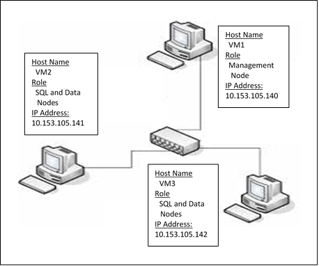
In this example, the following design will be implemented. One VM will host both the Cluster Manager and Client applications while the two remaining VMS will host the SQL and Data nodes. This is a minimal setup for an NDB cluster. However, for production environments, more nodes can be added to ensure the maximum high data availability for application users.
.
Creating the Virtual Machines (VMs)
1. Refer to Chapter X on how to create and configure a VM needed to setup a cluster. To implement the above architecture, you must have
3 VMs. Name these VMs as VM1, VM2 and VM3 (as shown above)
2. Once created a VM, do not forget to update the package information database using the command:
apt-get update
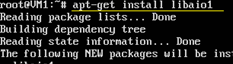
3. Download and install the dependency software:
apt-get install libaio1
.
4. Shutdown VM
Networking the Virtual Machines
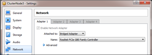
1. From the Oracle VirtualBox, right-click VM1 and click Settings…
2. From Settings, click Network
3. Click “Attached to” dropdown list, click “Bridged Adapter” and click OK
.
4. Repeat steps 1 to 3 for VM2 and VM3.
5. Start VM1, VM2 and VM3 and login as root
6. Know the IP of each VM using the command: ifconfig
In the output below, the assigned IP address for my machine is 10.153.105.5 but yours could be different.

.
The first 3 groups of numbers (also known as octets) in the IP addresses of the 3 VMs should be the same (e.g. 10.153.105). This means that they belong to the same network. They should only differ from the last number, which makes each of them unique in the network.
7. Write these IP addresses for your reference.
8. Test whether the 3 VMs are connected to each other using the command: ping IP-ADDRESS
Supposed that the VMs have the following addresses:
VM1 10.153.105.105
VM2 10.153.105.110
VM3 10.153.105.113
To test if VM1 and VM2 are connected to each other, from VM1, type the command:
ping 10.153.103.105.110 (press Enter)
If connected, you should see an output similar to the following:

.
This means that the VM1 got the reply from VM2 after 1.40 ms. Thus, the 2 VMs are connected to each other. However, the value could be different from yours. You may also test the connectivity between VM1 and VM3, etc.
Installing, Configuring and Starting the Cluster Management Node
Installing the Cluster Management Node
On VM1, we will install the Cluster Management Node.
1. Open VM1 and login as “root”
2. Create a directory named “download”.
mkdir download
3. Change directory to “download”
cd download
4. Copy the cluster installer which you have previously downloaded
cp /media/sf_shared/ mysql-cluster-gpl-7.4.11-debian7-x86_64.deb /root/download
5. Install the mysql cluster package:
dpkg –i mysql-cluster-gpl-7.4.11-debian7-x86_64.deb
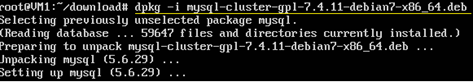
.
MySQL Cluster installation
directory is in /opt/mysql
You may verify the existence of
that directory using the command: ls /opt/mysql
The absence of an error message
basically means that your have successfully installed the software.
Configuring and Starting the Cluster Manager
1. Create a directory called “mycluster”
mkdir /var/lib/mycluster
We will store the cluster configuration file in this directory.
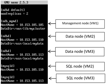
2. Create the cluster configuration file.
nano /var/lib/mycluster/config.ini
The
above command opens the “nano” editor with a new file named “config.ini”. Type the following:
.
3. Save the configuration file by pressing Ctrl + X > Y > Enter.
4. Start the cluster manager using the command:
/opt/mysql/server-5.6/bin/ndb_mgmd -f
/var/lib/mycluster/config.ini
The output should be similar to the following:

.
At this point, the cluster manager is up and running.
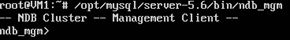
5. Open the management console using the command:
/opt/mysql/server-5.6/bin/ndb_mgm
The output should be similar to the following:
.
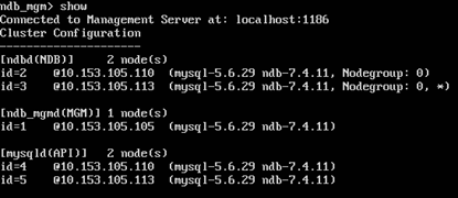
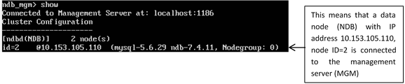
6. From the console, type the command:
show (press Enter)
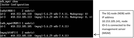
The output should be similar to the following:
.
The above output means that the cluster has:
- 2 NDB or data nodes running on VMs with the IPs 10.153.105.110 and 10.153.113.
- 2 API or SQL running on VMs with the IPs 10.153.105.110 and 10.153.105.113
- 1 MGM or management node running on VM with the IP 10.153.105.105
This is the partial implementation of the given Cluster Topology.
Keep the management node running.
Installing, Configuring and Starting the Data Node
Installing the Data Node
After setting and starting the cluster management node, the next task is to install and configure the 2 data nodes on VM2 and VM3.
To install the data node, please refer to the instructions given in “Installing the Cluster Management Node”. Do steps 1 to 5.
Configuring and Starting the Data Nodes
1. Open VM2 and login as “root”
2. Create a folder named “mydata” inside the /usr/local folder.
mkdir /usr/local/mydata
3. Create the data node’s (NDB) configuration file. This file will contain the setting for the NDB to connect to the management node (MGM).
nano /etc/my.cnf
In the nano editor, type the command as shown below. Save the file and exit from the editor.
.
The IP 10.153.105.105 refers to the Management Node.
1. Start the data node through the following command:
/opt/mysql/server-5.6/bin/ndbd
The output should be similar to the following:

.
The above output means that the data node was able to connect to the management node (10.153.105.105) through Port 1186 (default). The management node had allocated 2 as the data node’s unique ID in the cluster.
1. Switch to the management node (VM1) and type the command:
show (press Enter)
.
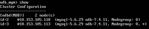
2. Do the same tasks on VM3. You may refer back to the following sections:
- Installing the Data Nodes
- Configuring and Starting the Data Nodes
The final output should be similar to the
following:
.
The two data nodes are now connected to the management sever.
Just keep the nodes running.
At this point, the management and data nodes are up and running. The final task is to install, configure and start the 2 SQL nodes on VM2 and VM3. The successful completion of these tasks will mean a successful completion of the basic MySQL NDB cluster.
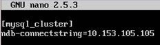
Configuring and Running the SQL Node
Configuring the SQL Node
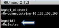
1. On VM2, open the configuration file named “my.cnf”
nano /etc/my.cnf
Add the following command:
.
2. Save the file and exit from the editor.
3. It is highly recommended that MySQL should run on its user (mysql) that belongs to its own group (mysql). Create the group using the command:
groupadd mysql
4. Create a user using the command:
useradd -r -g mysql -s /bin/false mysql
5. Create a default database
/opt/mysql/server-5.6/scripts/mysql_install_db --user=mysql
Running the SQL Node
1. Copy the startup script from /opt/mysql/server-5.6/support-files/mysql.server to the scripts directory:
cp /opt/mysql/server-5.6/support-files/mysql.server /etc/init.d/mysqld
2. Enable the script using the command:
systemctl enable mysqld.service
3. Start MySQL
systemctl start mysqld
4. The cluster installation path is /opt/mysql/server-5.6/bin/mysql. Create a symbolic link to it in the default /usr/bin path:
ln -s /opt/mysql/server-5.6/bin/mysql /usr/bin/
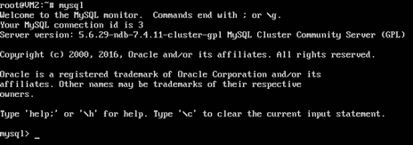
5. At this point, MYSQL Server is running at the background. Let’s use it using the command:
mysql
The output should be similar to the following:
.
6. Display the default databases using the command:
show databases;
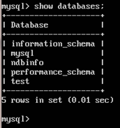
.
The presence of “ndbinfo” database in the list means that the SQL node has been successfully installed and configured.
7. Switch to VM1 and type the following command in the cluster management client:
show
The output should be:
.
8. Switch to VM3 and follow the same steps to Configure and Run the second SQL node.
After a successful installation, configuration and running of all the nodes, the following output should be seen from the cluster management client:
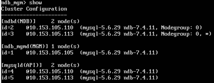
.
The cluster has the following running and connected components:
- 2 data nodes (NDB)
- 1 management node (MGM)
- 2 SQL nodes (API)
Testing the MySQL NDB Cluster
The purpose of this testing is to show that whatever changes made in one cluster data node immediately get copied to the other nodes.
1. In the SQL node of VM2, create a database named “hct”
mysql> create database hct;
2. Show the databases
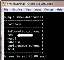
mysql> show databases;
The output should include the “hct” database.
.
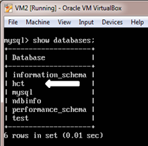
3. In the SQL node of VM3, show the databases.
mysql> show databases;
Notice that the “hct” database is also available from VM3. This clearly demonstrates the basic concept of synchronous data replication which is implemented through clustering.
.
4. In the same SQL node (VM3), create a table named “staff” in the “hct” database
mysql >
use hct;
mysql > CREATE TABLE Staff (id int, sname varchar(40), PRIMARY KEY (id)) ENGINE=NDBCLUSTER;
5. Insert a record into the Staff table and show the record.
mysql > INSERT INTO Staff
values(1,’Billy’);
mysql > SELECT * FROM Staff;
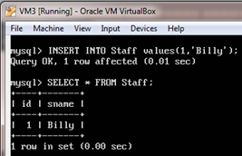
.
6. Now, verify whether the same actions have taken place in VM2. Switch to VM2 and show the records from the Staff table.
mysql > use hct;
mysql > select * from staff;
The output should be:
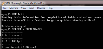
.
The output proved that the same
set of data can be accessed from any SQL node.
7. In the same VM2, Insert one more record into the Staff table:
mysql > INSERT INTO Staff values(2,’Bill’);